Pick up any inquiry that arrives at Pump Power Australia’s service counter and the scenario is almost always the same: the pump that failed was a centrifugal pump being used where a gear pump should have been specified years ago — or a gear pump that was correctly chosen for the original fluid but has been quietly pumping the wrong material for the past twelve months.
Gear pumps are among the most reliable and widely used industrial pump technologies in Australia — trusted across lubrication oil systems, fuel transfer, bitumen and asphalt handling, hydraulic fluid, chemical dosing, and food-grade oil processing. When correctly selected and maintained, a quality industrial gear pump delivers 20,000–30,000 hours of reliable service. When misspecified, it fails in weeks.
This guide — produced by the engineering team at Pump Power Australia, with over 35 years of experience supplying industrial gear pumps and pump solutions to Australian mining, marine, power generation, food, and chemical industries — gives you a practical, engineering-based framework for selecting the right gear pump for your specific application.
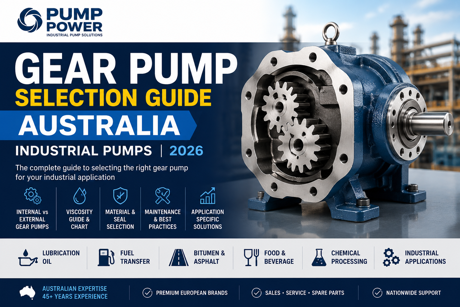
A gear pump is a type of positive displacement pump that moves fluid using two or more rotating, meshing gears. As the gears rotate, fluid is trapped between the gear teeth and the pump casing on the suction side, carried around the periphery to the discharge side, and pushed out as the gears mesh together. Gear pumps deliver consistent, pulsation-free flow regardless of discharge pressure — making them the preferred choice for viscous fluid transfer, precise metering, and dosing applications across Australian industry.
- How a Gear Pump Works — The Engineering Explained
- Internal vs External Gear Pumps — Key Differences
- Viscosity — The Most Critical Selection Factor
- Materials and Seal Selection Guide
- Australian Industry Applications — Which Gear Pump for Which Duty
- Gear Pump vs Other Pump Types — Full Comparison Tables
- Step-by-Step Gear Pump Sizing Guide
- Gear Pump Maintenance Guide and Inspection Checklist
- Common Gear Pump Problems and Troubleshooting
- Key Statistics — Gear Pumps in Australian Industry 2026
- Frequently Asked Questions (10 FAQs)
- Conclusion
1. How a Gear Pump Works — The Engineering Explained
The gear pump operating principle is one of the simplest in industrial pump technology — and one of the most reliable. Understanding it makes every selection and troubleshooting decision more intuitive.
The Operating Cycle
As the two gears rotate away from each other on the inlet side of the pump, a low-pressure zone (partial vacuum) is created. Atmospheric pressure pushes fluid from the suction line into the expanding space between the gear teeth.
Fluid trapped in the valleys between the gear teeth is carried around the outside of each gear — between the gear tooth face and the pump casing — from suction side to discharge side. The fluid is isolated from the inlet by the meshing gear teeth.
As the gears re-mesh on the discharge side, the space between the teeth is eliminated, forcing the trapped fluid out through the discharge port at the required pressure. The continuous gear rotation creates a smooth, near-continuous flow.
A fixed volume of fluid is displaced per revolution of the gear — this is the pump’s displacement (cm³/rev). Flow rate = displacement × RPM × volumetric efficiency. Unlike centrifugal pumps, flow rate does not fall as discharge pressure increases.
Why the Gear Pump’s Positive Displacement Principle Matters
- Consistent flow regardless of pressure — unlike a centrifugal pump, a gear pump’s output does not fall as back pressure rises, making it ideal for metering and dosing applications
- Self-priming — the low-pressure zone at the inlet enables the pump to draw fluid from below suction level without pre-filling
- Handles viscous fluids efficiently — volumetric efficiency improves as viscosity increases, because thicker fluid seals more effectively between gear teeth and casing
- Compact, high-pressure capability — achieves pressures far beyond what a centrifugal pump can reach in a comparable footprint
- VFD-compatible for flow control — flow rate is directly proportional to speed; VFD control provides precise output adjustment. Note: energy savings are proportional (linear), not cubic as with centrifugal pumps — see our VSD energy savings guide
Gear pumps rely on the pumped fluid to lubricate the internal gear faces, bearings, and shaft seal. Running dry — even briefly — causes rapid wear, seal failure, and potentially catastrophic gear damage. Always fit low-level protection on the suction source and never operate a gear pump without confirmed fluid at the inlet. For applications where dry running is a risk, consider a AOD pump — which tolerates dry running safely.
2. Internal vs External Gear Pumps — Key Differences
The first and most fundamental gear pump selection decision is between internal and external gear configurations. These are not interchangeable — each has distinct performance characteristics that make it better suited to specific duties.
| Factor | Internal Gear Pump | External Gear Pump |
|---|---|---|
| Design | Small inner gear (rotor) rotates inside larger outer ring gear; crescent seal fills the space between them | Two equal-size gears mesh externally and rotate in opposite directions; both driven or one drives the other |
| Viscosity range | Excellent across very wide range — 1 cSt to 1,000,000 cSt; preferred for very high viscosity duties | Best at 1–10,000 cSt; becomes less efficient at very high viscosities due to internal geometry |
| Shear sensitivity | Lower shear — preferred for shear-sensitive fluids (food oils, emulsions, polymers) | Higher shear — suitable for non-shear-sensitive fluids (fuel, hydraulic oil, bitumen) |
| Maximum pressure | Moderate — typically up to 20–35 bar depending on design | High — up to 200+ bar with close-tolerance design |
| Flow pulsation | Very low — smoother operation than external gear | Low to moderate — acceptable for most applications; can use helical gears for lower pulsation |
| Noise level | Quieter — preferred for noise-sensitive locations | Louder — especially at high speed and low viscosity |
| Maintenance | More complex — additional components (crescent, ring gear) | Simpler — fewer components; easier field maintenance |
| Capital cost | Higher — more complex machining | Lower — simpler design, more manufacturers |
| Ideal for | Food-grade oils, chocolate, resins, polymers, very high-viscosity fluids, quiet marine/power applications | Fuel oil, hydraulic oil, lube oil, bitumen, metering applications, high-pressure duties |
Choose internal gear pump when: viscosity >1,000 cSt, fluid is shear-sensitive, quiet operation is required, or food/pharmaceutical regulatory compliance is needed.
Choose external gear pump when: viscosity <1,000 cSt, high discharge pressure is required, simplest possible maintenance is the priority, or lowest capital cost matters most.
3. Viscosity — The Most Critical Gear Pump Selection Factor
Viscosity — the resistance of a fluid to flow — is the single most important parameter in gear pump selection. Unlike centrifugal pumps, which lose efficiency rapidly as viscosity increases, gear pump performance improves with viscosity up to a point — because thicker fluid seals more completely between gear teeth and casing, reducing internal slip.
Gear Pump Viscosity Selection Chart — Australian Industrial Fluids
| Viscosity range | Example fluids (Australian applications) | Gear pump suitability | Recommended type | Operating speed |
|---|---|---|---|---|
| <5 cSt | Water, light solvents, diesel | ⚠ Marginal — low viscosity fluid provides poor internal seal, high slip, low volumetric efficiency (60–75%). Centrifugal pump preferred | External (if must use gear pump) | Low RPM |
| 5–50 cSt | Light machine oil, kerosene, diesel fuel, petrol | ✅ Good — acceptable volumetric efficiency (80–88%). Common for fuel transfer and light lube oil duties | External gear pump | Medium RPM |
| 50–500 cSt | Hydraulic oil, gear oil, light lube oil, vegetable oil | ✅ Excellent — optimal range for most gear pumps. High volumetric efficiency (88–95%) | External or internal | Medium RPM |
| 500–5,000 cSt | Heavy gear oil, molasses, glycerol, glucose syrup, resins | ✅ Very good — excellent sealing, high efficiency (90–95%). Motor torque requirements increase; lower RPM required | Internal gear pump preferred | Low–medium RPM |
| 5,000–100,000 cSt | Heated bitumen, heavy fuel oil (HFO), polymer melts, honey | ✅ Good (heated pump required) — heating jacket on casing essential to maintain fluidity. Specify low speed and high-torque motor | Heated internal gear pump | Very low RPM |
| >100,000 cSt | Very heavy bitumen, cool polymer melts, very thick pastes | ⚠ Marginal — above 5,000 cSt, a progressive cavity pump or two screw pump may be more efficient | Specialist — contact Pump Power | Ultra-low RPM |
Viscosity changes dramatically with temperature. Bitumen that is solid at 15°C may have a pumpable viscosity of 500 cSt at 160°C. Heavy fuel oil at 40°C may be 1,000 cSt but only 100 cSt at 80°C. Always specify viscosity at the actual pumping temperature — and consider viscosity at both startup (cold) and steady-state (warm) conditions. A pump sized for 100 cSt at operating temperature may require a higher-torque motor to handle the cold startup viscosity. Contact Pump Power Australia for viscosity correction guidance.
4. Materials and Seal Selection Guide
Casing and Gear Material Selection
| Material | Best for | Avoid with | Australian applications |
|---|---|---|---|
| Cast iron | Petroleum products, lube oils, hydraulic fluid, bitumen — standard industrial duty | Corrosive acids, food contact, marine environments | Most common — lube oil, fuel transfer, bitumen at mine sites and industrial plants |
| 316 Stainless steel | Food-grade applications (FDA compliance), chemical service, marine environments, CIP-compatible | High-chloride environments (use duplex SS instead) | Food oils, syrups, chocolate, pharmaceutical, chemical processing, marine service |
| Ductile iron | Higher-strength general industrial duties — superior to cast iron for impact and pressure resistance | Same limitations as cast iron for corrosion | High-pressure hydraulic systems, mine site fuel transfer, heavy industrial duties |
| Hastelloy / Alloy 20 | Aggressive chemical service — sulphuric acid, hydrochloric acid, chlorinated solvents | Abrasive fluids | Chemical plant acid transfer, pH adjustment dosing in mining ane water treatment |
| Bronze | Saltwater and marine environments, low-abrasion duties | Ammonia, certain amines, abrasive fluids | Marine vessel fuel oil, seawater service, coastal industrial sites |
Seal Type and Material Selection
| Seal type | How it works | Best for | Limitation |
|---|---|---|---|
| Mechanical seal | Two flat rotating faces create a dynamic seal at the shaft exit | Most industrial duties — oils, chemicals, fuels. Lower leakage than packed gland | Sensitive to dry running and abrasive particles in fluid |
| Packed gland | Braided packing material compressed around shaft — slight seepage acceptable | General industrial duties where slight leakage is acceptable; lower initial cost | Not suitable for toxic, hazardous, or food-grade fluids where leakage is unacceptable |
| Magnetic drive (sealless) | Magnetic coupling transmits torque through sealed casing — no shaft penetration | Toxic, volatile, or high-value fluids where zero leakage is mandatory | Higher cost; not suitable for fluids with ferromagnetic particles |
Seal Elastomer Material Guide
| Elastomer | Temperature range | Best for | Avoid with |
|---|---|---|---|
| NBR (Nitrile) | -30°C to +100°C | Petroleum oils, fuels, hydraulic fluids, lube oils — standard choice for most industrial gear pump duties | Ozone, ketones, strong acids, aromatic hydrocarbons |
| Viton (FKM) | -20°C to +200°C | Solvents, aggressive chemicals, high-temperature oils, bitumen at elevated temperatures | Ketones, esters, amines, steam above 120°C |
| EPDM | -40°C to +130°C | Food-grade water-based products, CIP chemicals, phosphate esters | Petroleum oils, fuels, hydrocarbons |
| PTFE | -200°C to +250°C | Universal chemical resistance — used where no elastomer is compatible. Pharmaceutical and aggressive chemical duties | Molten alkali metals, fluorine gas (extreme conditions only) |
For mechanical seal selection guidance specific to your gear pump and fluid, contact Pump Power Australia’s technical team — we can advise on correct face material (carbon/SiC, tungsten carbide/SiC) and elastomer combination for your application.
5. Australian Industry Applications — Which Gear Pump for Which Duty
Lubrication Oil Systems
Gear pumps are the dominant technology in industrial lubrication systems across Australian mining, power generation, and manufacturing. Their ability to maintain consistent flow across varying oil viscosities (thin when hot, thick when cold) makes them ideal for main engine lubrication circuits, gearbox lube supply, and turbine seal oil systems.
- Specify: cast iron or ductile iron casing, steel gears, NBR seals for standard lube oil. For synthetic lubricants at elevated temperatures, Viton seals are recommended
- Key consideration: size for cold-start viscosity — lube oil at 5°C may be 10× more viscous than at operating temperature; motor must handle the startup torque
- Filtration: always install a suction strainer (minimum 125 micron) and consider a fine discharge filter on precision lubrication systems
For very high-pressure lube oil and quiet marine applications, triple screw pumps (Allweiler, IMO) may be preferred over gear pumps — see our marine application page.
Fuel Transfer and Handling
Fuel transfer applications across Australian mining sites, transport depots, aviation facilities, and power stations are one of the most common gear pump duties. Diesel, aviation turbine fuel, and heavy fuel oil (HFO) are all well-suited to external gear pump technology.
- Diesel and light fuel oil: external gear pump, cast iron casing, NBR seals, carbon/SiC mechanical seal
- Heavy fuel oil (HFO) at elevated temperature: heated external gear pump, Viton seals, heating jacket connected to steam or hot oil
- ATEX/IECEx hazardous area: for fuel transfer in classified areas, use an explosion-proof motor or consider a pneumatically driven AOD pump that requires no electricity
Bitumen and Asphalt Transfer
Heated gear pumps are the standard technology for bitumen and asphalt transfer in Australian road construction and refinery applications. At operating temperatures of 150–200°C, bitumen viscosity drops to a pumpable range (typically 200–1,000 cSt), making internal or external gear pumps with heating jackets the correct choice.
- Specify: heating jacket on pump casing and gland area (steam or thermal oil circuit); Viton or high-temperature NBR seals; carbon steel or ductile iron for standard bitumen; stainless steel for polymer-modified bitumen
- Critical: always maintain heating while the pump is stationary — bitumen solidifies in the pump body rapidly when temperature drops, making restart impossible without melting the pump out
- Alternative: for bitumen emulsions at lower temperatures, a progressive cavity pump may handle the emulsion without heating requirements
Chemical Dosing and Metering
The gear pump’s consistent, pressure-independent flow makes it ideal for chemical dosing and metering applications — where the volume delivered per unit time must be accurate and repeatable regardless of downstream pressure variations.
- Polymer addition in water treatment: stainless steel internal gear pump, VFD control for precise dose rate adjustment
- Resin and adhesive transfer: heated internal gear pump, Viton seals, temperature-controlled discharge
- Ink and coatings: stainless steel, high-polish finish, mechanical seal compatible with solvent-based fluids
- Toxic chemical metering: sealless magnetic drive gear pump — zero leakage by design. See our chemical transfer application page
Food-Grade Oil and Syrup Processing
Internal gear pumps in food-grade 316 stainless steel are widely used for edible oil, chocolate, glucose syrup, and similar food and beverage processing duties. The internal gear design provides lower shear than external gear pumps — protecting product quality in oil and syrup transfer.
- 316 SS casing, gears, and shaft — AS4020 food contact material compliance
- Food-grade EPDM or NBR seals — FDA-compliant elastomers
- Electropolished internal surfaces (Ra ≤ 0.8 µm) for CIP compatibility
- For shear-sensitive food products (creams, emulsions, fruit products), a lobe pump or eccentric disk pump may be preferred over a gear pump
Marine and Power Generation
Gear pumps are standard equipment on commercial vessels and in power generation facilities for fuel oil booster service, seal oil supply, and hydraulic oil transfer. For main engine lube oil and turbine lube oil service where extremely quiet, pulse-free operation is required, triple screw pumps from Allweiler or IMO are often preferred over gear pumps in critical machinery room applications.
6. Gear Pump vs Other Pump Types — Full Comparison Tables
Table: Gear Pump vs Centrifugal vs Progressive Cavity vs Screw Pump
| Factor | Gear Pump | Centrifugal Pump | Progressive Cavity | Triple Screw |
|---|---|---|---|---|
| Best viscosity range | 50–5,000 cSt (optimal) | <100 cSt | 1–1,000,000 cSt | 0.6–100,000 cSt |
| Solids handling | Poor — abrasive particles damage gears | Moderate (slurry pump variants) | Excellent — up to 70% by weight | Poor — clean fluid only |
| Discharge pressure | High — up to 200+ bar | Moderate (multistage for high pressure) | Moderate (multi-stage for higher) | High |
| Shear on fluid | Low to moderate | High | Very low | Very low |
| Self-priming | Yes | No | Yes — excellent suction | Limited |
| Flow pulsation | Low | None | Very low | None (pulse-free) |
| Metering accuracy | Excellent | Poor | Excellent | Excellent |
| VFD energy savings | Proportional (linear) | Cubic (50% at 80% speed) | Proportional (linear) | Proportional (linear) |
| Maintenance complexity | Low to moderate | Low | Moderate (stator wear) | Low |
| Typical Australian use | Lube oil, fuel, bitumen, food oils, chemical metering | Water, low-viscosity fluids, high flow | Sludge, mining slurry, food with solids | Marine lube/fuel oil, power station |
For a complete comparison of centrifugal and positive displacement pump types, see our dedicated guide: Centrifugal Pump vs Positive Displacement Pump — Which One Does Your Application Need?
7. Step-by-Step Gear Pump Sizing Guide
Correct gear pump sizing prevents the most common and costly installation failures — underperformance, motor overloading, and premature wear. Follow these six steps systematically. For complex applications, contact Pump Power Australia’s engineering team — we provide free sizing support.
- Define required flow rate (L/min or m³/hr)
Establish minimum, normal, and peak flow requirements. Gear pump flow = displacement (cm³/rev) × speed (RPM) × volumetric efficiency. Higher viscosity improves volumetric efficiency (90–95%); lower viscosity reduces it (75–85%). Always design for the maximum required flow. - Calculate total system pressure (bar)
Total system pressure = static head (bar) + pipe friction losses + back pressure from downstream equipment. Add a 15–20% safety margin. Remember: a pump delivering 100 L/min at 5 bar may only deliver 85 L/min at 50 bar — confirm performance at operating pressure from the pump curve. - Confirm fluid viscosity at operating temperature (cSt)
This is the most critical and most frequently missed step. Measure or confirm viscosity at the actual pumping temperature — not ambient. Check cold-start viscosity separately and confirm the motor can handle startup torque at cold-start conditions. - Select pump type and operating speed (RPM)
Use the viscosity chart in Section 3 to select internal vs external gear pump type. For high-viscosity fluids, specify lower operating speed — higher speed at high viscosity generates excessive heat and wear. As a general guide: below 500 cSt, run at 1,000–1,450 RPM; 500–5,000 cSt, reduce to 500–900 RPM; above 5,000 cSt, consider 200–500 RPM maximum. - Specify materials of construction and seal type
Use the material selection tables in Section 4 to specify casing, gear, and seal materials based on fluid chemistry, temperature, and regulatory requirements (food-grade, ATEX, API). Confirm compliance requirements with your procurement and HSE team before finalising. - Size the motor (kW)
Motor power (kW) = (flow rate in L/min × pressure in bar) ÷ (600 × pump efficiency × motor efficiency). As a rule of thumb, allow 20–25% motor oversizing above the calculated duty power to handle startup torque at cold viscosity and future process changes. Never undersize the motor — gear pump motor overloading is a primary cause of catastrophic pump failure.
Pump Power Australia’s engineering team provides free gear pump sizing and selection support for all customers. Tell us your flow rate, operating pressure, fluid type, viscosity at operating temperature, and any special requirements (food-grade, ATEX, heating jacket) — and we will recommend the right pump, motor, and materials for your application. Enquire online or call +61 3 9933 7400.
8. Gear Pump Maintenance Guide and Inspection Checklist
Quality industrial gear pumps — correctly specified, correctly installed, and correctly maintained — regularly achieve 20,000–30,000 hours of service life. The number one cause of premature failure is not mechanical design weakness — it is contamination of the pumped fluid with abrasive particles. A USD $200 suction strainer can prevent a USD $8,000 gear pump failure.
| Frequency | Maintenance task | What to look for | Action if found |
|---|---|---|---|
| Daily | Visual check for leaks; listen for noise; check inlet/outlet pressure gauges; verify operating temperature | Fluid weeping at seal = seal wear. Grinding or rattling = gear or bearing issue. Abnormal pressure rise = blockage downstream | Shut down for seal or internal inspection; do not operate with leaking seal in toxic or food service |
| Weekly | Check suction strainer differential pressure; inspect coupling alignment; verify relief valve setting | High strainer differential = blockage. Coupling misalignment = vibration, bearing wear, seal stress | Clean or replace strainer element; realign coupling if misalignment is confirmed |
| Monthly | Performance benchmark — record flow, inlet/outlet pressure, motor current at fixed operating point | Declining flow at constant speed = gear wear and increasing slip. Rising current = viscosity increase or blockage | Compare trend to baseline — plan inspection or replacement before performance becomes unacceptable |
| Quarterly | Bearing lubrication; shaft runout measurement; gear tooth and casing wear inspection if accessible | Bearing overheating; unusual vibration signature; gear face surface roughening or pitting | Replace bearings if vibration or temperature signatures are abnormal; replace gear set if pitting is evident |
| Annual / major service | Full strip and inspect: gear teeth, casing wear, bearing clearances, seal faces, shaft condition | Gear face wear beyond clearance tolerance = volumetric efficiency loss. Casing scoring = replacement needed | Full rebuild or replacement as required. Contact Pump Power Spares & Services |
9. Common Gear Pump Problems and Troubleshooting
| Problem | Most likely cause | Corrective action |
|---|---|---|
| Flow rate declining at constant speed | Internal gear wear — increasing clearances allow more internal slip (recirculation) | Benchmark against baseline. If progressive trend, plan gear replacement. Check for contamination in fluid that may be accelerating wear |
| Pump will not prime or fails to draw fluid | Excessive suction lift; air leak on suction line; suction strainer blocked; fluid viscosity too high at cold start | Check suction line for leaks and blockages. Verify suction lift is within pump rating. Pre-heat fluid if cold-start viscosity is very high |
| Excessive noise and vibration | Cavitation (insufficient suction pressure); gear tooth damage from solid particle ingestion; coupling misalignment; bearing failure | Check suction conditions and NPSH margin. Inspect strainer for solids. Check coupling alignment. Inspect bearings and gear teeth on shutdown |
| Mechanical seal leaking | Seal face wear; wrong elastomer for fluid (swelling or hardening); dry running damage; misalignment causing seal face distortion | Replace seal. Confirm seal face and elastomer material compatibility with fluid chemistry. Check shaft alignment. See our Mechanical Seals page for replacement options |
| Motor overloading / tripping | Fluid viscosity higher than specified (wrong temperature); downstream blockage causing excessive back pressure; relief valve not opening correctly | Measure actual fluid viscosity. Check downstream pipework for blockage. Test and reset relief valve. If viscosity is consistently higher than specified, upsize motor |
| Excessive heat generation | Pump running against closed or partially blocked discharge (relief valve bypassing); operating speed too high for fluid viscosity; fluid viscosity higher than rated; insufficient cooling | Check discharge line is fully open. Verify operating speed is appropriate for viscosity. Add cooling jacket or heat exchanger in bypass circuit if overheating is persistent |
10. Key Statistics — Gear Pumps in Australian Industry 2026
| Statistic | Source / context |
|---|---|
| Gear pumps handle viscosities up to 1,000,000 cSt in specialist configurations — the widest applicable viscosity range of any common pump type | Roper Pump Company / GlobalSpec technical references, 2025–26 |
| External gear pumps achieve up to 200+ bar discharge pressure — making them the highest-pressure option in the standard rotary PD pump category | GlobalSpec Gear Pumps Selection Guide |
| Gear pump volumetric efficiency at optimal viscosity range (21–600 cSt): 90–95%. At very low viscosity (<5 cSt): 60–75% | NAPCO Pumps sizing guide technical data, 2026 |
| Gear pump service life with correct selection and maintenance: 20,000–30,000 hours (5–7 years continuous operation) | ISOHITECH industrial lubrication pump guide, June 2026 |
| Contamination (abrasive particles in fluid) is the #1 cause of premature gear pump failure — ahead of overheating, speed, or design issues | ISOHITECH / Roper Pump technical literature, 2026 |
| Australia industrial pump market CAGR 2025–2033: 6.9% — energy efficiency and smart monitoring are primary growth drivers | IMARC Group Market Research, 2026 |
| Gear pumps are used in >90% of Australian excavators and construction machinery lubrication systems — the most universally adopted lube oil pump type | ISOHITECH lubrication system guide, 2026 |
| Pump Power Australia stocks gear pumps and spare parts from our Brooklyn, VIC warehouse — available for fast dispatch nationally across Australia | Pump Power Australia, 2026 |
Key Takeaways
- Gear pumps deliver consistent, pulsation-free flow regardless of discharge pressure — making them ideal for viscous fluid transfer, metering, and dosing
- Choose internal gear pumps for high-viscosity, shear-sensitive, food-grade, or quiet operation duties; choose external gear pumps for fuel/oil transfer, high-pressure duties, and simplest maintenance
- Viscosity at operating temperature — not ambient temperature — is the most critical specification input; always measure at the actual pumping temperature
- Gear pumps must never handle abrasive solids — for solids-containing fluids, specify a progressive cavity pump or slurry pump
- Gear pumps must never run dry — always install low-level protection on the suction source
- The optimal viscosity range for most industrial gear pumps is 50–5,000 cSt — outside this range, consider alternative pump types
- Contamination is the #1 cause of premature gear pump failure — always fit a suction strainer (minimum 125 micron) and maintain it regularly
- Motor sizing must account for cold-start viscosity, which may be many times higher than operating-temperature viscosity
- Heated gear pumps with heating jackets are the correct specification for bitumen, asphalt, HFO, and other high-pour-point materials
- Pump Power Australia supplies a comprehensive range of industrial gear pumps with free engineering selection support — call +61 3 9933 7400
Frequently Asked Questions
Structured for Google People Also Ask, ChatGPT, Gemini, Claude, and Perplexity direct answer extraction.
A gear pump is a positive displacement pump that moves fluid using two or more rotating, meshing gears. As the gears rotate, fluid is trapped between the gear teeth and the pump casing on the suction side, carried around to the discharge side, and pushed out as the gears mesh together. Gear pumps deliver consistent, pulsation-free flow regardless of discharge pressure, making them ideal for viscous fluid transfer, metering, and dosing. They are a form of positive displacement pump — unlike centrifugal pumps, flow rate does not fall as back pressure rises.
An external gear pump uses two equal-size gears that mesh externally — best for fuel, lube oil, and hydraulic fluid at low-to-medium viscosity, achieving pressures up to 200+ bar. An internal gear pump uses a smaller inner gear rotating inside a larger outer ring gear with a crescent seal — better for high-viscosity fluids (edible oils, chocolate, resins, polymers), quieter operation, and shear-sensitive applications. Internal gear pumps are generally preferred for food-grade duties; external gear pumps for high-pressure industrial service. Contact Pump Power Australia for application-specific guidance.
Gear pumps handle fluids from approximately 1 cSt (light solvents) up to 1,000,000 cSt (very heavy bitumen and polymer melts) in specialist configurations. The optimal range for most industrial gear pumps is 50–5,000 cSt — light to heavy oils, hydraulic fluids, and edible oils — where volumetric efficiency reaches 90–95%. Below 5 cSt, internal leakage increases and efficiency drops significantly, making a centrifugal pump more appropriate. Above 5,000 cSt, a progressive cavity pump may offer better performance. Always specify viscosity at operating temperature — not ambient.
No — standard gear pumps are not suitable for fluids containing suspended solids or abrasive particles. The close-tolerance meshing gear design is vulnerable to rapid wear and damage from solid particles. For fluids containing solids, a progressive cavity pump (up to 70% solids by weight) or a slurry pump is the correct choice. Gear pumps are best suited to clean or mildly contaminated viscous fluids — oils, fuels, bitumen, syrups, resins.
Food-grade gear pumps require FDA-compliant wetted materials. Specify: 316 stainless steel casing and gears (standard food-grade material compliant with AS4020); food-grade EPDM seals for water-based products and CIP chemicals; food-grade NBR seals for edible oils and fats; electropolished internal surfaces (Ra ≤ 0.8 µm) for hygienic cleanability. For shear-sensitive food products where product quality is the priority, a lobe pump may be preferred over a gear pump. See our food and beverage application page.
The three main options are: (1) Mechanical seal — preferred for most industrial duties; lower leakage than packed gland; specify carbon/SiC faces for oils and fuels, tungsten carbide/SiC for abrasive or aggressive fluids; (2) Packed gland — simple, low cost, suitable where slight leakage is acceptable in non-hazardous, non-food applications; (3) Magnetic drive (sealless) — for toxic, volatile, or high-value fluids where zero leakage is mandatory. Select elastomer material (NBR, Viton, EPDM, PTFE) based on chemical compatibility. See our mechanical seals page.
Gear pump sizing requires five inputs: (1) required flow rate (L/min or m³/hr at maximum demand); (2) total system pressure (bar) including static head, pipe friction, and back pressure; (3) fluid viscosity at operating temperature (cSt); (4) fluid temperature range; (5) fluid chemical composition for material selection. Calculate: motor power (kW) = (flow × pressure) ÷ (600 × pump efficiency × motor efficiency). Allow 20–25% motor oversizing for cold-start torque. Contact Pump Power Australia — we provide free gear pump sizing support to all customers.
With clean fluid, correct viscosity, proper suction filtration (minimum 125-micron strainer), and correct installation, quality industrial gear pumps achieve 20,000–30,000 hours (5–7 years continuous operation). The primary causes of premature failure are: contamination of fluid with abrasive particles (the #1 cause), dry running, cavitation from insufficient suction pressure, and incorrect seal material. A well-maintained gear pump in clean service is one of the most reliable pump technologies available. Contact our Spares & Services team for spare parts and refurbishment support.
Yes — heated gear pumps with heating jackets are the standard technology for bitumen and asphalt transfer at Australian road construction and refinery sites. At operating temperatures of 150–200°C, bitumen viscosity drops to a pumpable range (200–1,000 cSt). Specify: heating jacket on casing and gland connected to steam or hot oil supply; Viton or high-temperature NBR seals; carbon steel or ductile iron for standard bitumen grades; stainless steel for polymer-modified bitumen. Always maintain heating while the pump is stationary — bitumen solidifies in a cold pump rapidly, making restart impossible. See our asphalt and emulsions application page.
Yes. Pump Power Australia supplies a comprehensive range of industrial gear pumps for lubrication oil, fuel transfer, bitumen, food-grade, chemical dosing, and hydraulic fluid applications from our Brooklyn, Victoria warehouse. We stock spare parts and provide rapid dispatch to customers across Victoria, Western Australia, Queensland, New South Wales, South Australia, and the Northern Territory. Our engineering team provides free gear pump selection and sizing support for all enquiries. Call +61 3 9933 7400 or enquire online.
Conclusion: Selecting the Right Gear Pump for Your Australian Industrial Application
Gear pumps are among the most reliable, versatile, and widely used pump technologies in Australian industry — but only when correctly selected and maintained. The framework in this guide — choosing by viscosity, fluid chemistry, pressure requirement, and regulatory context — gives engineers, plant managers, and procurement teams across Australian mining, food processing, marine, power, and chemical industries a systematic basis for making the right decision.
The key messages are consistent: internal gear pumps for high-viscosity and shear-sensitive duties; external gear pumps for fuel, oil, and high-pressure service; always specify viscosity at operating temperature; always fit a suction strainer; never run dry; and size the motor for cold-start torque, not just operating-condition power.
Pump Power Australia supplies a comprehensive range of industrial gear pumps backed by free engineering selection support, local spare parts inventory, and pump refurbishment and servicing capability from our Brooklyn, Victoria base. Whether you need a food-grade stainless steel gear pump for edible oil processing, a heated unit for bitumen transfer on an Australian road site, or a standard lube oil gear pump for a mining machine lubrication system — our team can specify, supply, and support the right solution.
Need Help Selecting the Right Gear Pump for Your Application?
Talk to Pump Power Australia’s engineering team. Tell us your fluid, viscosity, operating pressure, and application — and we will recommend the right gear pump, seal type, and materials for your specific industrial duty. Free sizing support for all enquiries.
📞 +61 3 9933 7400
✉ info@pumppower.com.au
9 Export Drive, Brooklyn VIC 3012 | pumppower.com.au/contact-us
Serving industrial customers across Victoria, Western Australia, Queensland, New South Wales, South Australia, and the Northern Territory.
This article was prepared by the engineering team at Pump Power Australia, a specialist industrial pump supplier based in Brooklyn, Victoria, with over 35 years of experience supplying gear pumps, progressive cavity pumps, centrifugal pumps, and pump solutions to Australian mining, oil and gas, marine, food and beverage, water treatment, and chemical processing industries.
Pump Power Australia supplies pump solutions to major Australian operators including BHP, Rio Tinto, Shell, and Woodside. Our team provides independent pump selection advice backed by hands-on application experience across Australia’s most demanding industrial environments.
References and External Sources
- Roper Pump Company — “Choosing the Right Gear Pump for High-Viscosity Fluids” (July 2025): roperpumps.com
- Roper Pump Company — “Understanding Industrial Gear Pump Technology and Selection Considerations” (June 2026): roperpumps.com
- GlobalSpec — “Gear Pumps Selection Guide: Types, Features, Applications”: globalspec.com
- NAPCO Pumps — “How to Size a Rotary Gear Pump” — 5-step engineering sizing guide: napcopumps.com
- ISOHITECH — “3 Types of Oil Pumps for Lubrication Systems: Engineering Selection Guide” (June 2026): isohitech.com
- Taha Industries — “How to Choose the Best Gear Pumps for Applications” (February 2026): tahaindustries.in
- IMARC Group — Australia Industrial Pumps and Valves Market Research 2025–2033: imarcgroup.com
- Pump Industry Magazine Australia — State of the Industry 2026: pumpindustry.com.au
- Australian Government Department of Energy — Motor and pump efficiency guidance: energy.gov.au
- Food Standards Australia New Zealand (FSANZ) — Food contact materials compliance: foodstandards.gov.au